February 13, 2020
Background
Doppler Velocity Logs (DVLs) have been an industry standard for underwater navigation for a number of year now. Whether the vehicle is a Remotely Operated Vehicle (ROV), Autonomous Underwater Vehicle (AUV), Unmanned Underwater Vehicle (UUV) or manned vehicles such as submarines, DVLs are used to determine underwater position to navigate. Work-class ROVs have become a mainstay in the Oil and Gas market allowing for work such as opening and closing valves and conducting surveys to be done deep below the sea surface. Observation class ROVs are currently used for a wide range of applications. AUVs have become a popular choice for pipeline and hull inspections as well as search and rescue and even military applications such as explosive ordinance disposal (EOD). AUVs and UUV have similar applications as ROVs, but have the advantage of not being tethered, which allows for longer distance deployments, such as survey/bathymetry, velocity mapping, military surveillance as well as many others. Manned vehicles have obvious military applications as well as observation and scientific uses that require knowledge of underwater location/position. It’s safe to say that the underwater navigation market has grown significantly over the last 10-years and will continue to grow to support the Oil and Gas and Military and other scientific related markets.
How it works
A DVL essentially measures velocity over the bottom of a vehicle by sending pings from four transducers (transceivers) at a known frequency. The frequency change from the acoustic reflection off of the bottom measured at the transducers/transceivers is used to determine velocity over bottom or vehicle velocity reference to the bottom. The DVL knows when pings are sent and received to determine vehicle velocity; additionally, time between pings is used to determine distance traveled (distance = velocity * time). In a simplistic view, underwater navigation requires a heading sensor such as a compass for direction and is coupled with DVL data for velocity, distance and direction. The velocity data is given in 3 dimensional space. So you will know how far you traveled in X, Y an Z. So from your start location you can determine where you traveled underwater in a 3D space. DEAD RECKONING
The image below represents a spectrum on SeaPILOT DVL products.
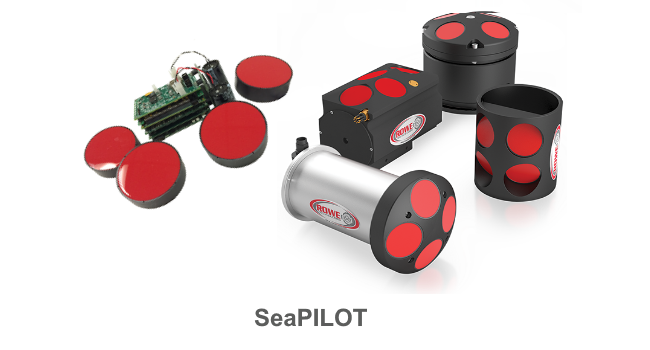
SeaPILOT Enclosures Available
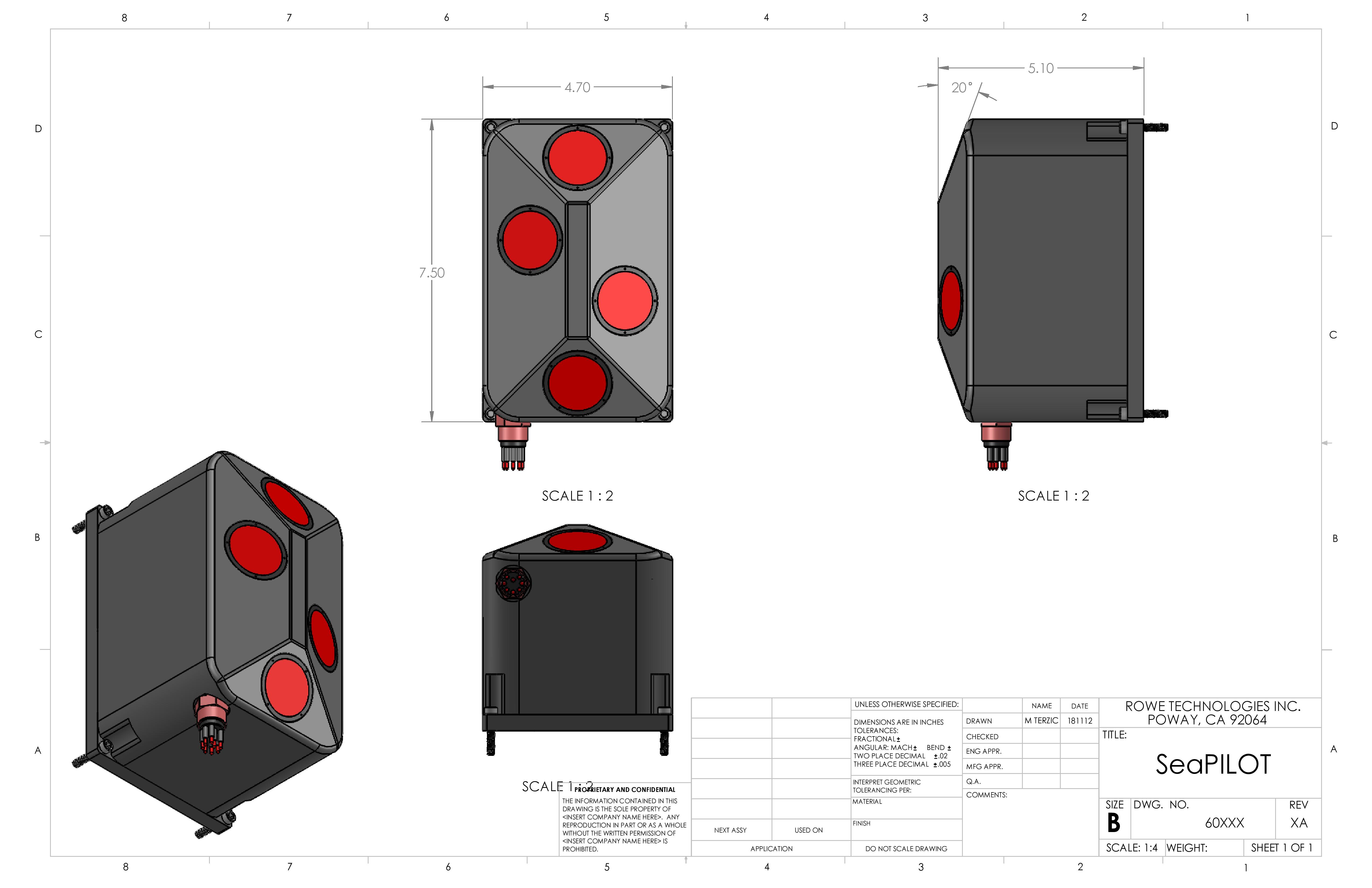
Capsule
Smallest Package:5.0in x 9.3in (OD x Height)
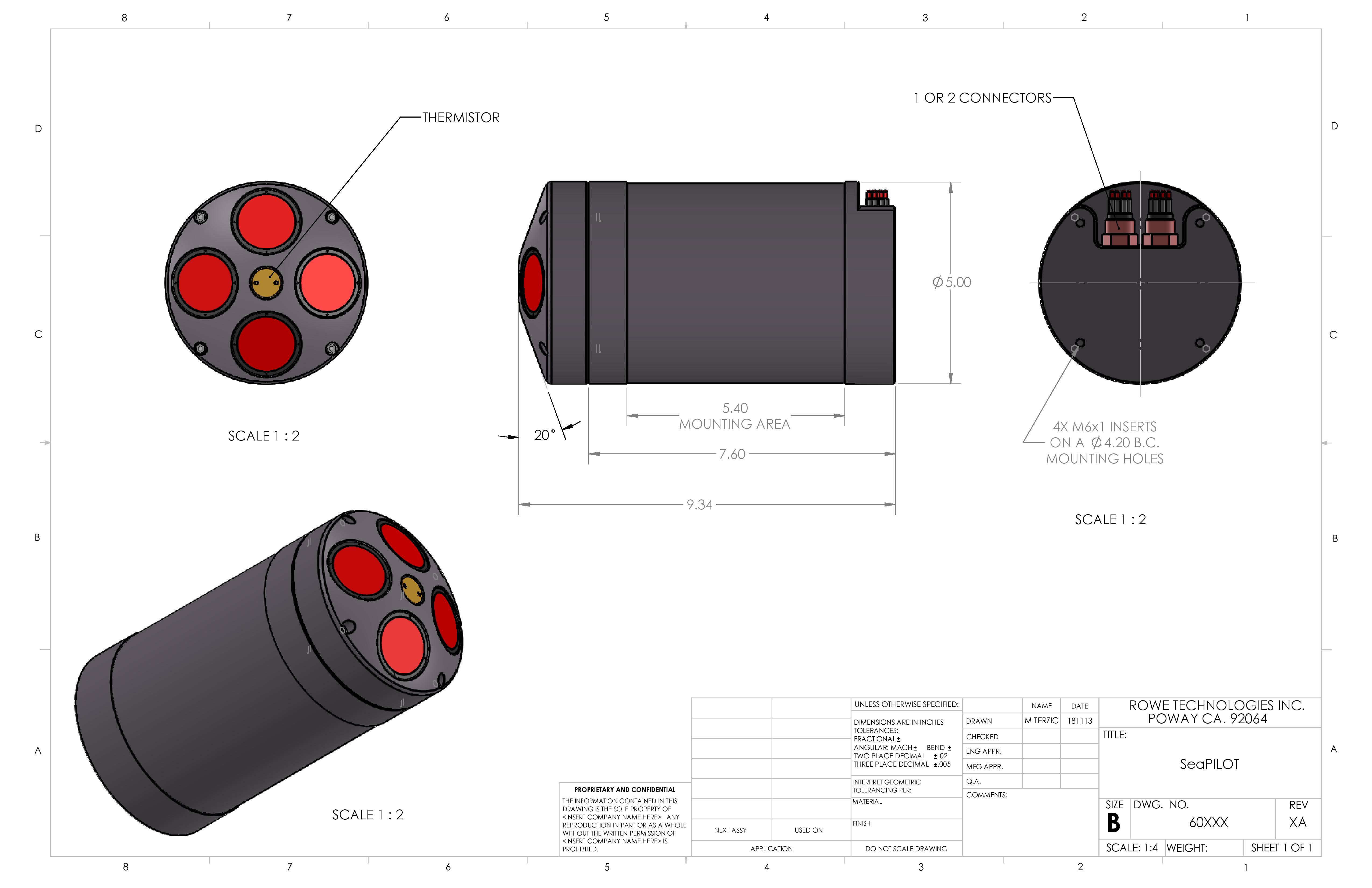
Cylindrical
Smallest Package:4.5in x 12.5in (OD x Length)
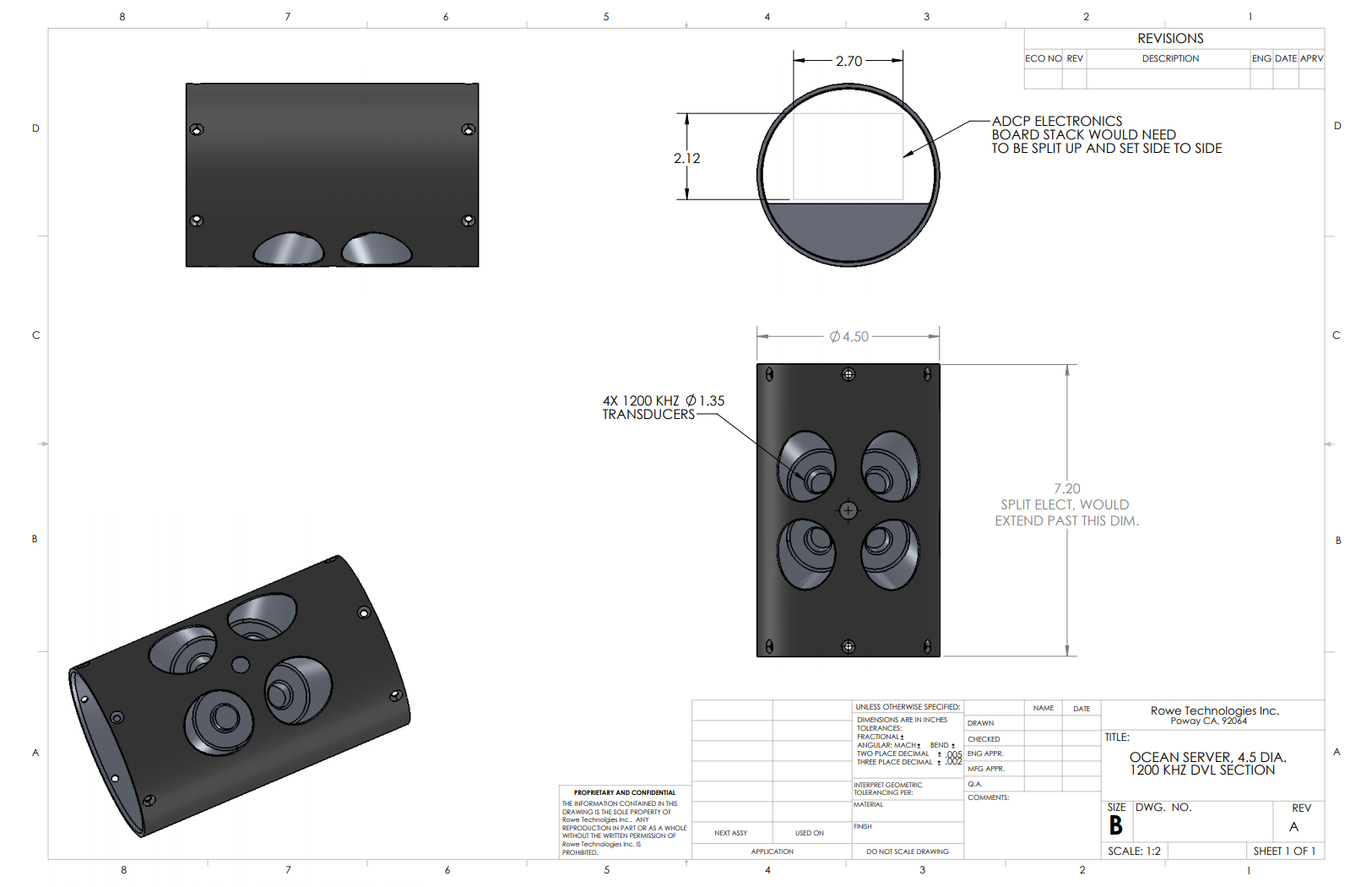
Flat-Pack
Smallest Package:5.0in x 7.5in x 5.1in (LxWxH)
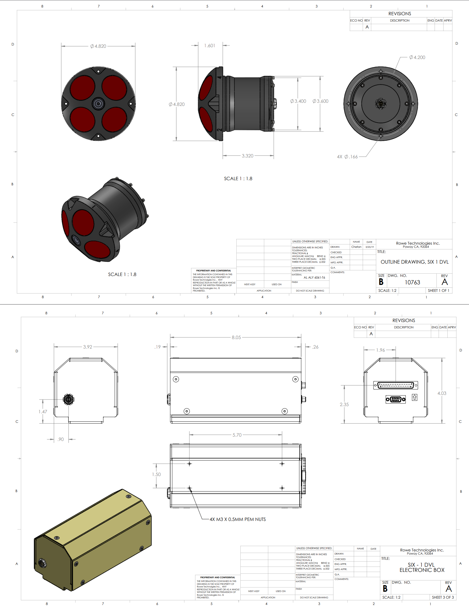
Remote Head
Head: 4.82in x 4.92in (OD x Height)Electronics: 8.05in x 3.92in x 4.03in (LxWxH)
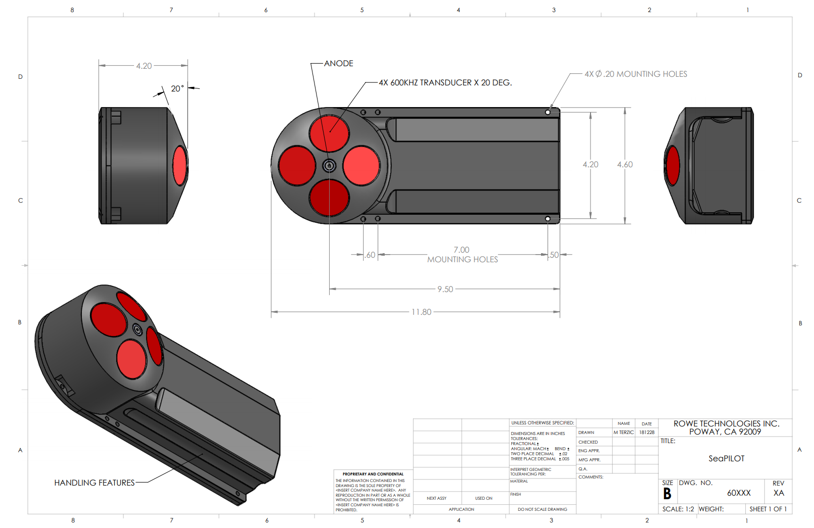
Low Profile
11.8in x 4.6in x 4.2in (LxWxH)Data from the field
A few simple tests were conducted with a SeaPilot 600 KHz DVL at Lake Miramar in San Diego, California. The goal of these tests is to highlight the accuracy of the data collected by the DVL. Data from the DVL will be compared to reference GPS data. GPS data was collected using a Hemisphere V102 GPS Compass. Table 1 presents the configuration of the DVL and the GPS Compass. Prior to collecting data with the DVL, the DVL’s internal compass was calibrated and the magnetic declination was entered – this is done to mitigate any potential differences between the DVL’s heading and the GPS Compasses heading.
The GPS is used as our baseline reference unit. The Hemisphere V102 GPS is specifically used because it includes a heading value. This will allow us to test the ADCP’s speed and direction with a single reference unit. Also because this type of GPS is readly available to most user, this same test can be performed by others in the field to verify installation of there DVL or ADCP.
The salinity is set to 0ppt in this setup because the test is done in a lake. The lake is good controlled environment. If you are running this test in the ocean, please set the salinity to 35ppt CWS 35.
| DVL Configuration | |||
|---|---|---|---|
| Magnetic Declination | +12.05° | CHO 12.05 |
CHO - Heading Offset |
| Ping Rate | 5 Hz | CEI 00:00:00.20 |
CEI - Ensemble Interval |
| Salinity | 0 ppt | CWS 0.0 |
CWS - Water Salinity |
| Save | CSAVE |
CSAVE - Save changes | |
| Start Pinging | START |
START - Start pinging | GPS Configuration |
| Lat/Lon | $GPGGA | $JASC,GPGGA,2 |
Enable $GPGGA at 2 Hz |
| Heading | $GPHDG | $JASC,GPGGA,2 |
Enable $GPHDG at 2 Hz |
| Velocity | $GPVTG | $JASC,GPVTG,2 |
Enable $GPVTG at 2 Hz |
| Save | $JSAVE |
Save changes and wait for $>SAVE COMPLETE response. |
Command File
CDEFAULT
CEI 00:00:00.20
CHO 12.05
CWS 0
CSAVE
START
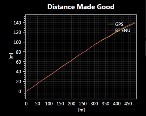
Straight Line Test
To test the installation and calibration of the DVL, a straight line run is conducted. We conduct this test routinely at a local lake. A lake is better than the ocean for this test, because there is no swells or strong currents that can cause any cross-track. This test aims to show the accuracy of the DVL when compared to a GPS with a compass. Figure 2 below presents the data collected at Lake Miramar of a straight line run. For this test, the GPS compass measured 477.0 m, while the DVL measured 477.2 m. This gives an error of 0.04%. This test is run at least 2 times with the ADCP in 2 orientations. Beam 0 is orientated front of the boat for the first test run. The test in this orientation will mainly test beams 0 and 1. The ADCP is then rotated 90 degrees so Beam 3 is foward and the same test is run. When moving Beam 3 forward, the heading between the ADCP and the GPS will be offset by 90 degrees, because the compass is no longer facing forward like the GPS. For a DVL to pass, the error must be less than 1.0%.
| DMG (Distance Made Good) Test Results | |
|---|---|
| DMG GPS | 477.0 m |
| DMG DVL | 477.2m |
| Percent Difference | 0.04% |
Percent Error = ((measured - correct) / correct) * 100
Correct = GPS measurement
Measured = ADCP measurement
These test results were collected using Pulse software. This same test can be run at anytime by a user.
Rowe Technologies DVL solutions
Rowe Technologies Inc. (RTI) is backed by over two centuries of man-years experience and manufactures DVLs and ADCPs. RTI provides DVL solutions for shallow coastal applications (Delrin housing) down to full ocean depth (Titanium housing). In addition, RTI’s has DVLs specifically for working class and observation class ROVs. In additional, RTI offers an OEM package for end users that have highly customized end products.
More topics and tutorials can be found at Rowe EDU
For more information about Rowe Technologies DVLs, please visit:
http://rowetechinc.com/seapilot/
sales@rowetechinc.com
+1 (858) 842 3020.